Rolling Element
The role of the bearing is to reduce friction between objects and make the process of rolling smoother. The foundational principles existed long before bearings came into being. Consider how people moved large stones in ancient times: wooden strips were placed under these objects to slide them around more easily. In the same way, bearings have moving components called
Rolling Element, which is the first largest component that makes up the bearing.
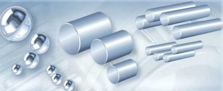
Due to the heavy loads involved in industrial applications, the rolling elements are typically made of high-carbon steel with a hardness of at least 670HV. These rolling elements are mainly divided into two categories: Ball and Roller.
As their monikers imply, steel balls are used in ball bearings, while strip-shaped rollers are employed in roller bearings. Ball bearings came into being earlier and are much more widely adopted. Roller bearings are further subdivided into two, namely: Cylindrical Roller Bearing, those generally with a roller diameter greater than 5 mm, with a roller length to diameter ratio of under 3, and Needle Roller Bearing, those generally with a roller diameter under 5 mm, with a roller length to diameter ratio greater than 3.
SJB mainly produces needle roller bearing and cylindrical roller bearing. The term "needle roller bearing" has broad and narrow terms of usage — the narrow sense refers to the above description, while the broader definition encompasses cylindrical roller bearings as well. For the sake of this article, please bear in mind the broader sense of the term.
Cage
If the rolling elements are not held in place, these will inevitably collide and generate friction, thereby failing in the intended purpose. Element called
Cage is thus employed to restrict the movement of rolling elements and ensure that they roll in a consistent pattern. The cage itself is made of either metal or plastic. Though the window-blasting process has been employed more frequently, welding has been increasingly used in this area. The cage is the second largest component that makes up the bearing.
The
Needle Roller and Cage Assembly developed by the German inventor Georg Schaeffler in 1949 involves a set of needle rollers and a cage. The radial section of the bearing is equivalent to the diameter of the needle. These bearings are suitable for applications with a very small radial design envelope, but high load and speed requirements — such would be the case in the connecting rod of a piston car engine. This particular method of assembly remains prevalent in the industry, catering to a wide spectrum of applications.
Radial Bearing and Axial Bearing
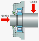
Before delving deeper into other modern forms of bearings, understanding the direction of bearing stress, namely radial and axial, is essential.
Radial direction refers to the vertical line formed along the diameter or radius, which is perpendicular to the axis. Axial direction refers to the line that runs across the axis. Bearings that are subject to radial loads, called Radial Bearing, are typical of the aforementioned needle roller and cage assembly. Bearings that are subject to axial loads, called Axial Bearing, are typical of the Thrust Needle Roller and Cage Assembly described below.
The thrust needle roller and cage assembly differs from the conventional assembly method in that the resulting bearings have a construction that is flat and can carry high axial loads and axial shock loads in one direction, but must not be subjected to radial loads which must be supported by means of an additional bearing. The axial section height corresponds only to the needle diameter and is equivalent to the radial section in the conventional needle roller and cage assembly. These bearings typically have use cases in which axial space is extremely limited — consider a car's electronic parking brake system.
Raceway Ring
Bearings consisting of two parts, needle rollers and a cage, typically have a similar construction: the needle rollers are the only objects between Shaft and Housing. Since needle rollers are hardened rolling elements, contact area of shaft and housing need to be of the same hardness, otherwise these adjacent parts would be easily worn down after a duration of use. To overcome this, most bearings are designed with a Raceway Ring, which is the third largest component of a bearing.
In the case of a ring-shaped radial bearing, a raceway ring mounted on the inside of the bearing is called an
Inner Ring, while a raceway ring mounted on the outside of the bearing is called an
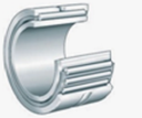
Outer Ring. Inner ring and outer ring are typically made from hardened steel tubes, and through a process of grinding. Needle bearings featuring an outer ring and a removable inner ring (i.e. the bearing can be supplied with or without an inner ring) are referred to as
Machined Needle Roller Bearing. Among these are ones that have a thicker outer ring, called
Track Roller Bearing, and these are used in cam drives, bed rails, conveyor equipment and the like.
In the case of a planar axial bearing, the raceway ring is often referred to as a
Washer (also known as a Race). A washer mounted on one side of the shaft, and rotating along with the shaft, is called a
Shaft Locating Washer. A washer that is mounted on the side of the housing but does not rotate is called a
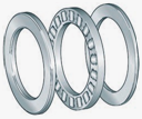
Housing Locating Washer. Depending on the thickness of the gasket, it can be divided into punched parts and solid parts. The punching washers produced at SJB are usually between 0.5 mm and 1.6 mm thick. There is also a series of nonstandard gaskets developed for customers with anti-rotation function. The thickness of the solid washers is typically over 1.7 mm. A custom series of ranked washers developed by SJB has 5 um divided into one rank. Nonstandard washers and ranked washers are mainly used in automotive air-conditioning compressors, which is a major focus area for SJB. A set of washers, including a thrust needle roller and case assembly, forms a
Thrust Needle Roller Bearing, also known as a Axial Needle Roller Bearing.
Drawn Cup Roller Clutch
When it comes to the raceway ring of the bearing, there is a thin-walled drawn outer ring that's unique to needle roller bearings, and this is referred to as a Drawn Outer Cup. Unlike a solid outer ring, drawn outer cup is formed by multiple stamping and stretching of thin steel sheets, and the wall thickness is about 1 mm (the add thickness difference is under 0.01 mm).
Note that this in particular is an internal standard by SJB. These specifications can be achieved with an annular cylinder. When the annular cylinder is used to make a one-way clutch, it is necessary to machine a series of ramps on the inner wall to match the nylon cage and spring plate installation. This is an undertaking that SJB has excelled at.
A bearing made from a drawn outer cup with a series of slopes inside is called a
Drawn Cup Roller Clutch. Each of the needles has an independent spring plate that transmits one-way torque. When the direction of the external force coincides with the direction of locking, the blocking function immediately takes effect. On the other hand, when the force comes from the opposite direction, the bearing idles. This product can be assembled into a indexing clutch, a backstop clutch and an overrunning clutch for a wide range of applications, including automotive engine systems, automotive brake systems, washing machines and air conditioners.
Drawn Cup Needle Roller Bearing
A drawn outer cup is combined with a needle roller and cage assembly or a set of needle rollers to form a typical Drawn Cup Needle Roller Bearing. This type of bearing requires no additional means of axial retention (as a result of which the housing bore is easy to produce). This makes the mounting of such bearings simple and economical, and is the most widely used type of needle bearing.
Drawn cup needle roller bearings are further divided into two types: closed end and open ends. The former is used for closing off the shaft ends and protecting the bearings against contamination and moisture. The latter often acts as the main bearing, in such cases as automotive power steering. Certain open type bearings do not feature a cage and only use a special grease to retain the maximum number of needle rollers. This is called a
Full Complement Drawn Cup Needle Roller Bearing. These bearings can offer extremely high load carrying capacity. However, they do not permit the speeds that are possible when drawn cup needle roller bearings are used in conjunction with rolling elements retained by a cage.
In short, needle roller bearings tend to have small radial section sizes, while being able to withstand great radial loads. When cases call for great axial loads, then these can be combined with thrust needle roller bearings. This compact design is ideal for situations in which space is limited, but loads and speeds are high.
Suzhou Jincheng Bearing Co., Ltd.

 Rolling Element
 Cage
Cage Needle Roller & Cage Assembly
 Radial & Bearing
 The Thrust Needle Roller & Cage Assembly
 Machined Needle Roller Bearing
 Inner Ring
 Thrust Needle Roller Bearing
 Nonstandard Thrust Needle Roller Bearing
 Drawn Cup Roller Clutch
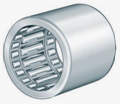 Drawn Cup Roller Clutch with Bearing
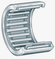 Drawn Cup Needle Roller Bearing
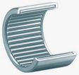 Full Complement Drawn Cup Needle Roller Bearing
